


Experimental and numerical analysis of free surface deformation in an electrically driven flow

Abstract
The present paper presents the experimental and numerical results of an electrically induced flow in a cylindrical container (188 mm diameter) filled with a In–Ga–Sn alloy. The electric current is applied from copper electrodes of various diameters (4–8 mm) and varied from 100 to 700 A. The deformation of the free surface just under the electrode is reported in term of depth. At some critical current an arc develops around the electrode tip. To explore numerically what happens in such flows, calculations of the Magnetohydrodynamic (MHD) flow are performed. The numerical model is based on a potential formulation for the electromagnetic field. The evolution of the free surface flow is tracked with a VOF model. The electromagnetic parameters are fully coupled with the evolution of the free surface and the contact surface at the electrode. At low current density the interface is shifted downward by the pinch action of the Lorentz force. In the same time the rotational part of the Lorentz force drives the liquid metal flow in radial direction towards the electrode. The flow is accelerated towards the electrode and sinks in the form of a strong jet. At the high current density, the velocities are strong enough to induce further displacement of the interface by a Bernoulli mechanism. The combined action of the pinch and the rotational components of the Lorentz force on the interface displacement, scales as I2. The numerical and experimental results are in good agreements.
Graphical abstract
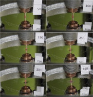
Surface of the liquid metal for the case of 5 mm electrode diameter. A plastic gain of pink colour surrounds the tip of the electrode. The applied DC current is 50, 100, 150, 250, 300 and 350 A. Circular waves are visible for I > 250 A. A dark area near the electrode appear when the cavern becomes deep and wide enough. For I = 350 A an arc appears around the electrode tip.
Keywords
- Ampere's force;
- Lorentz force;
- Magnetohydrodynamic;
- Free surface;
- Electric current;
- Liquid metal;
- Arc;
- Jet;
- Electric arc furnace;
- Pinch
1. Introduction
Electrically induced flows are present in many industrial processes such as Electroslag remelting, Vacuum arc remelting, electrolyzers, electric arc furnaces, smelting and aluminium reduction cells. The flow in such system is generated by the interaction of the electric current with the self-magnetic field. In these processes the interfaces between metal/electrolyte or electrode/Plasma are deformed by the electromagnetic force. Large difference in electric conductivity exists between the phases, metals are typically 103–105 times more conducting than the electrolyte and the plasmas. If an electric current density is exceeded a strong coupling could exist between the electric current distribution and the phase distribution. The study of the mechanism of generation and development of the flows generated within a current carrying fluid due to the interaction of an electric current with a self-magnetic field is important in order to gain correct understanding of these engineering processes. In spite of the practical significance, some essential features of these flows have not yet been explored.
One of oldest reference of an experiment showing the deformation of an interface was described by Northrup [15]. In one of his experiment he used a box of various cross section filled with a layer of liquid potassium–sodium. When a sufficiently strong horizontal current is applied, the level of liquid metal decreases vertically in the narrow section of the box. This phenomena is also known as Magnetohydrodynamic (MHD) “pinch effect”, it is an instability in which the conductor constricts itself until severed. More recently Graneau [5] studied force generated by the application of a current in a propulsive seawater jet engine. To illustrate the mechanism, he considers an experiment in a cup filled with liquid mercury where a current was applied between an immersed copper rod and a copper ring. The rod was located in the bottom of the cup, and the ring just underneath the surface. A jet was generated and caused the surface to rise in the middle of the cup giving the aspect of a liquid mercury fountain. It was also shown that the jet propulsive force is proportional to the square of the current.
Simulation with interface movement under the action of electric current are mainly found in the field of aluminium reduction cells [2], [3], [14] and [22] and Electroslag remelting process [6], [7] and [10]. Several mathematical models have been developed to simulate the hydrodynamics and the interface deformation. The most popular model is based on the “shallow layer” theory, motivated by the fact that the depth of the liquid layers are much smaller than the horizontal dimensions of the process. Full simulations in 3D are still challenging in term of numeric and calculation time [8].
The experimental investigation of flows in industrial processes is hindered by the fact that, due to high temperatures and chemical aggressiveness of the slag/cryolite, accurate direct measurement of the velocity are very difficult.
Attempts have been made to validate the numerical model used in the present work, with data collected in literature [9]. The validation aimed to numerically reproduce the intriguing experimental observations made by Bojarevics [1] on the appearance of swirl in flows in an electrically induced flow. The experiment consisted in supplying an electric current to a small water-cooled electrode of 0.8 cm diameters, in the centre of a free surface mercury filling a hemispherical copper container, 36 cm in diameter, which represents the other electrode. The electrode is electrically insulated in most of its length except over a short distance below the free surface. When the electric current is applied from above the free surface, a converging flow is set up. The flow is coupled with a rotation. No rotation is observed when the current is supplied from below the free surface. The prediction of the main features such as the deformation of the free interface as well as the swirl generation was in agreement with the experimental observation. The main conclusion was that the earth magnetic field had indeed a strong influence on the flow. Any analysis of an electrically induced flow should carefully account for the influence of external magnetic fields even as small as the one generated by the earth [21].
For the sake of further validation, new experiments and simulations were performed. The present paper presents an investigation of an electrically induced flow generated within a cylindrical container. In opposite to the Bojarevics [1] experiment, the electrode has spherical tip. Before the experiment the tip is fully immerged in the liquid metal, once a current is applied the interface starts to deform. To understand the physical mechanisms involved in these experiments, selected simulations were performed with a 2D MHD–VOF numerical model.
2. Experimental procedure
The experiment consists in filling a hemispherical container with the galistan alloy. A spherically tipped electrode is dipped within the liquid metal so that the entire tip is entirely in contact with the liquid metal. The experimental procedure and the dimensions of the facilities are given in Fig. 1 and Fig. 2. The current is applied from the top, and leaves from the bottom by traveling over a vertical wire strictly aligned with the electrode. The deformation of the interface is observed and measured optically with an optical camera. To obtain a good visibility of the electrode tip an angle of view of about 26° is set between the horizontal plane and the axis of the camera (Fig. 1).
